CTS Turbo Connecting Rods VW 164×20 I-Beam Rifle Drilled | Fits 3.2L 24V VR6 and 2.8L 12V and 24V VR6

Code: CTS-CRI-16420

US$749.99

In Stock
Included Warranty

12 Months
All CTS Turbo products are warrantied against manufacturing defects for a period of 12 months from the date of invoice. Warranty does not cover abuse, misuse, consequential damages, normal wear and tear, improper installation, or damages resulting from racing. Warranties only apply to the original owner. If a product is found defective the customer will receive, at the discretion of CTS Turbo, free repair or replacement. Warranty on other manufacturers will be processed under their terms.

Description

We are excited to announce our 164×20 rifle drilled drop-in connecting rods for VR6 engines designed to work with stock or aftermarket pistons. Our connecting rods have been engineered for larger turbo and boost applications while maintaining reliability.

Rifle Drilled

All CTS connecting rods are rifle drilled as standard. Factory rod bearings are not drilled but can be used. Drilled bearings are no longer available from the manufacturer.

Honing

All big and small end bores are honed in house on precision equipment to exacting tolerances.

Quality Control

All connecting rods are put through a stringent quality control process including measuring all critical dimensions on our state of the art CMM (coordinate measuring machine). All connecting rods are matched in weights +/- 1 gram.
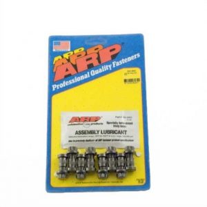
ARP Bolts

All CTS Turbo connecting rods come standard with genuine ARP 2000 rod bolts.

Product Specifications

  • Center to Center: 164mm
  • Wrist Pin Diameter: 20mm
  • Big End Journal Width: 19.9mm
  • Wrist Pin Style: Non-tapered
  • Big End Journal Diameter: 50.60mm
  • Rod Bolt Dimensions: 5/16″

Fitment

  • 12V VR6 2.8L
  • 24V VR6 2.8L
  • 24V VR6 3.2L

Additional information

Weight 14 lbs
Dimensions 12 × 8 × 6 in

SPECS

TECHNICAL SPECIFICATIONS

ABCD

164MM

50.6MM20MMARP 2000

INSTALL SUPPORT

Verify Clearances


Before installing your CTS connecting rods it is recommended you measured all the critical clearances. Make sure to record the measurements for each rod and number match them to the bearing set, crankshaft journal, and wrist pins.

** You must use a quality bore gauge and micrometer, record the following measurements:**

  • Wrist pin diameter
  • Wrist pin bushing bore
  • Wrist pin clearance (Bore minus diameter
  • Rod journal (w/bearings)
  • Crankshaft journal diameter
  • Journal clearance 


Torque Specifications

STEP 1 -PRE-TORQUE:

Before you final stretch the rod bolts, it’s important the bolt and rod threads are fully seated.

  • Install rod bearings
  • Align matching printed numbers on rod and cap
  • Assemble cap to rod
  • Apply ARP assembly lube to bolt threads
  • Hand tighten bolts
  • Using a quality calibrated torque wrench, torque bolts to 50 ft/lbs
  • Break bolts loose, and again torque to 50 ft/lbs
  • Break bolts loose, then torque to 50 ft/lbs one final time

STEP 2 -FINAL TORQUE:
The final torque spec is .006″ (stretch gauge) or 50 ft/lbs (torque wrench) with ARP assembly lube. The preferred method of measuring bolt load is with a stretch bolt gauge.

Stretch Gauge

  • Loosen bolt and zero stretch gauge
  • Tighten bolt to .006″ stretch
  • Loosen second bolt and zero stretch gauge
  • Tighten second bolt to .006″ stretch

Torque Wrench

  • Loosen bolt
  • Tighten bolt to 50 ft/lbs
  • Loosen second bolt
  • Tighten second bolt to 50 ft/lbs

Important notes

  • Do not exceed rod bolt stretch/torque. If bolt stretch is exceeded, replace rod bolts with new ones.
  • Torque wrench settings are given as a guide only, to ensure proper bolt installation a stretch gauge is required.
  • Do not install bolts dry or with any other lubricant than the supplied ARP assembly lube.